Sensor and wiring
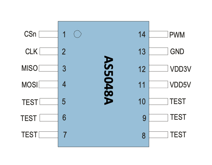
The SPI interface uses SCK, MOSI, MISO, and active-low CSn.
Connect the sensor and controller grounds, use a supply and logic levels that
meet the datasheet, place decoupling close to the device, and keep the magnetic
and mechanical assembly within the specified tolerances. The pinout above is
an IC reference, not a board-specific wiring diagram.
The AS5048A also exposes a PWM output, but this library communicates only over SPI. The driver does not configure the PWM pin, program OTP, or abstract board power control.
Magnet placement
Use a diametrically magnetized two-pole magnet centered above the package. Air gap, lateral displacement, tilt, magnet strength, nearby ferromagnetic material, and shaft runout all affect accuracy. Check the diagnostic flags and AGC value during mechanical validation rather than treating a plausible angle as proof of correct alignment.
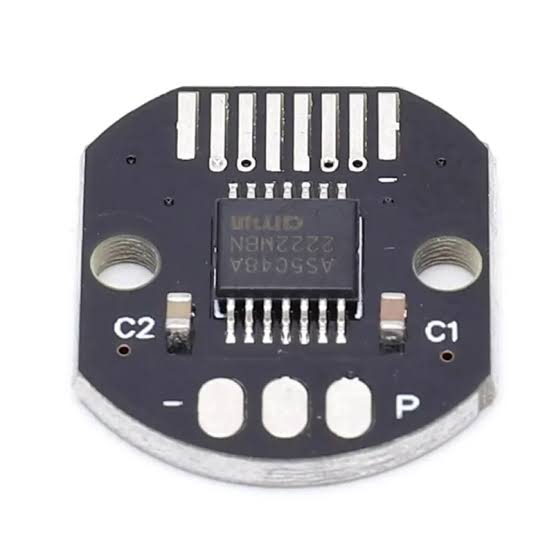
Consult the AS5048A datasheet for
the authoritative pin functions, absolute maximum ratings, recommended
operating conditions, timing, magnet requirements, and package drawings.